So, with the engine being lowered sufficiently to make the hood close, this created the little problem of the front steering linkage. The center link and the crankshaft want to occupy the same space :). Lowering the center link with a different pitman arm and idler arm is not a viable solution since the bump steer will be out of this world. The inner tie rods need to be more/less in the same location as they were to keep proper steering/suspension geometry relationships.


In the above pictures, you can see that the original center link actually ran above the cross member so it was more/less straight, however the crossmember modifications and reinforcement would require a different solution. A centerlink from a 1 ton Ford van happened to be in the scrap bin at the shop so it was selected to live another life. The diameter was ~1.125″ vs the original of ~0.75″ so significantly stronger, which would be necessary.
Samples from both the donor and original bar were sent out for metallurgical analysis to be able to properly weld and heat treat the final product.
The ends of the 1996 center link were cut off to retain the same interface for the tie rod ends. Pitman and idler arms were sourced from a mid 90’s Chevy truck which provided a stronger interface for extended life/durability as well as much more common replacement parts. The tapered ends were reamed out to fit these larger components.


The Ford center link had plenty of extra length which was used to make the W shape and spacers. This allowed the center link to connect the two tie rod ends, idler and pitman arms wile clearing the engine. The tie rod grease zerks are very close to the oil pan at the spindle stops. The oil pan reinforcing ribs were relieved to allow them to clear! The steering travel will be reduced slightly to prevent tire rub and allow a bit more safety margin at full lock.


Once the assembly was tacked together, clearances and functionality verified, a brace was welded on to keep everything true as it was welded out. The material was preheated and inerpass temperatures were maintained by alternating sides and using sterno cans.


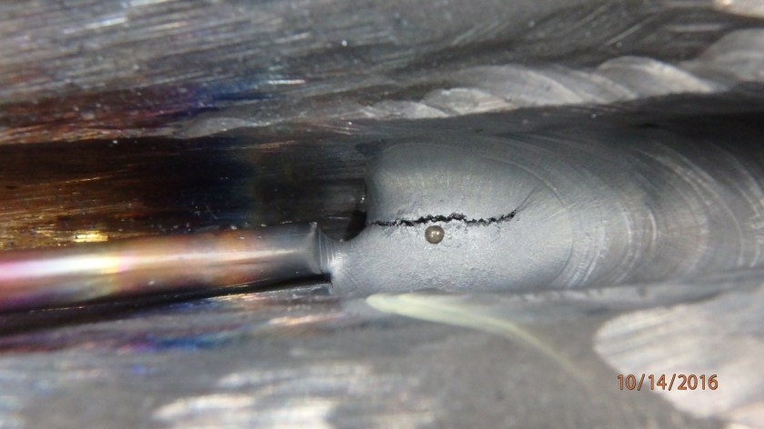
This is what happens when medium carbon steel cools too quickly! The circuit breaker on the TIG welder tripped in the middle of the weld. Don’t worry – this was ground out and re-welded.
Welding was done with a TIG welder for full penetration on the root passes and then wire for subsequent filler passes. All filler material was ER80S. Immediately after welding, the whole assembly was boxed up in fiberglass insulation and allowed to cool slowly. Even 24 hours later it was still warm to the touch!
After this, it was ground smooth to eliminate any burrs and make it look nice. The weldment was then sent out to a heat treating company to be stress relieved and then quenched/tempered to the original material specifications. Samples from the heat treated weldment were cut off and verified that the material properties were the same as the original OEM samples.
Next up the steering column!
